



Dung sai và độ đồng tâm của chốt đục lỗ để dập ổn định
Punch pin tolerance and concentricity affect more than the measured diameter of a component. A punch point can meet its size tolerance and still sit off-center relative to the shank, retainer, or die opening. That error changes local punch-to-die clearance and can lead to uneven loading, wear, burr variation, deflection, or premature damage.
The punch must therefore be evaluated as part of a complete locating system. The shank fits into the retainer, the point enters the die opening, and the surrounding die components maintain alignment during each stroke. The broader roles of these parts are covered in SunshinePro’s Hướng dẫn thành phần khuôn (suy luận). This guide focuses specifically on how punch dimensions, geometric relationships, drawing controls, and inspection methods support stable stamping.
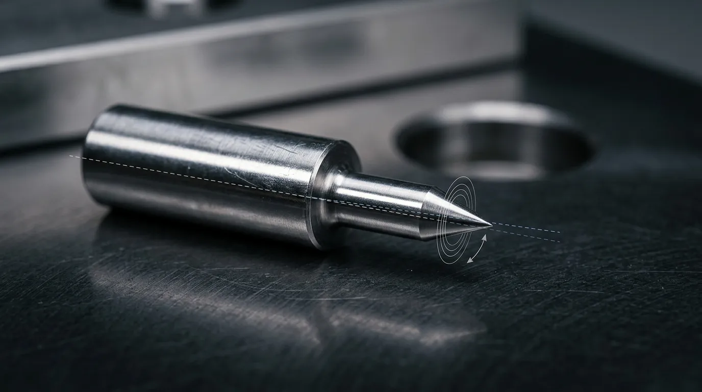
What Punch Pin Tolerance Actually Controls
A dimensional tolerance defines how much a stated size may vary. On a punch pin, separate tolerances may apply to:
- Punch-point diameter or cutting profile
- Shank diameter
- Chiều dài tổng thể
- Point length
- Vị trí vai
- Head or retention features
A geometric tolerance controls something different. It may limit the form of one feature, the orientation or location of one feature relative to another, or the variation of a surface when the part rotates around a datum axis.
This distinction matters because size tolerance does not automatically control alignment.
A punch point and shank may both be within their specified diameter limits while their centerlines remain offset. The shank may also be slightly bent, the point may be ground at an angle, or a cylindrical surface may be out of round. None of those conditions is fully described by diameter tolerance alone.
Why Diameter Tolerance Alone Is Not Enough
Consider a stepped punch with a locating shank and a smaller cutting point. Each diameter can be acceptable when measured independently. However, if the point axis is offset from the shank axis, rotating the punch around the shank will cause the point surface to move toward and away from the indicator.
The punch is within size tolerance, but it may not remain centered in the die opening.
The drawing must therefore answer two separate questions:
- Is each feature the correct size?
- Is each feature in the correct geometric relationship to the functional reference?
That reference is often the shank or another locating feature that represents how the punch is installed in the retainer.
Concentricity, Coaxiality, Runout, and Position Are Not Interchangeable
“Concentricity” is often used informally to describe how well the punch point aligns with the shank. In formal geometric dimensioning and tolerancing, however, the word can have a more specific meaning.
The applicable drawing standard must be identified before deciding which term or control is correct. ASME Y14.5 defines dimensioning and tolerancing practices for drawings governed by the ASME system. Tiêu chuẩn ISO 1101 provides the geometrical-specification framework used on ISO-based drawings.
| Term or control | Nó mô tả gì | Practical punch relevance | Common interpretation risk |
|---|---|---|---|
| Độ đồng tâm | A relationship between centers or derived median points relative to a datum axis, depending on the governing standard | May appear on legacy or customer-controlled drawings | Often confused with a simple indicator reading |
| Tính đồng trục | The condition of two features sharing the intended axis | Useful concept for point-to-shank alignment | May be used descriptively without a complete drawing definition |
| Độ lệch tâm | Physical offset between nominally common centers or axes | Describes how far the punch point is displaced from the shank reference | Must be clear whether the reported value is radial offset or full indicator movement |
| Circular runout | Surface variation measured at individual circular sections during rotation around a datum axis | Useful for controlling local rotational variation | Includes more than center offset because surface form also affects the reading |
| Total runout | Cumulative surface variation over a controlled length during rotation | Useful when the full cylindrical surface relationship matters | Can be unnecessarily restrictive if only one section is functionally important |
| Chức vụ | Location of a feature or feature axis relative to defined datums and basic dimensions | May be appropriate for locating punch or die features | Does not automatically control all surface-form variation |
| Tiểu sử | Size, shape, location, and sometimes orientation of a contour | Important for non-round punches | Centering alone does not control the complete cutting profile |
A dial indicator normally reports surface displacement during rotation. That result is commonly expressed as runout or total indicator reading, or TIR. It is not automatically equivalent to formal GD&T concentricity.
Thuộc tính Viện Tiêu chuẩn và Công nghệ Quốc gia explains that runout controls can reflect both axis-related displacement and surface-form effects. An indicator reading may therefore include eccentricity, roundness error, fixture error, surface defects, and the way the datum is simulated.
Why the Drawing Standard and Revision Matter
A geometric callout has meaning only within its governing standard and revision. A legacy customer drawing may use concentricity differently from a newly created ASME-based drawing. An ISO-controlled drawing may also use a different specification framework.
Do not silently replace one control with another because it is easier to inspect. The designer, supplier, and inspector should agree on:
- The governing standard and revision
- The datum feature
- The controlled feature
- The numerical limit
- The inspection method
- The reporting convention
How the Punch–Retainer–Die Tolerance Chain Affects Alignment
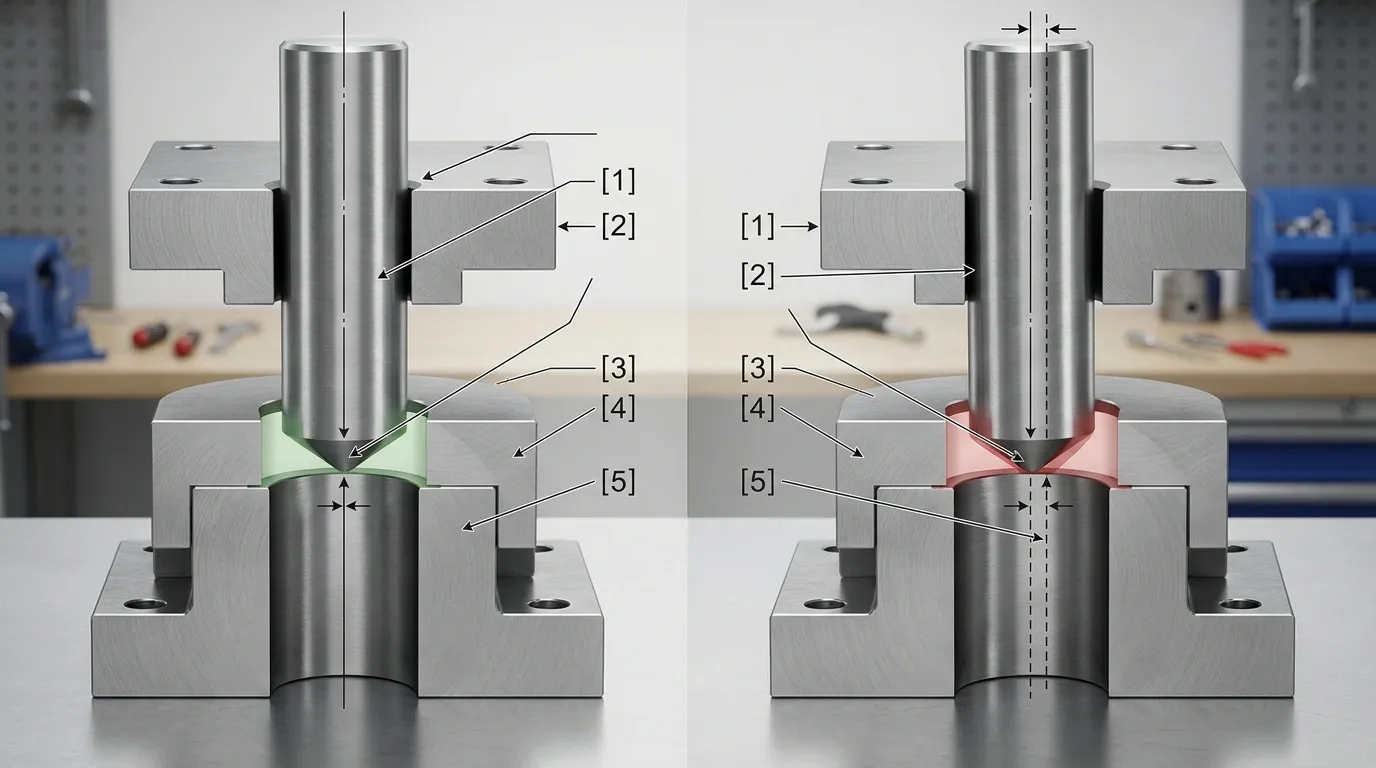
Punch alignment is not determined by the punch alone. Several component relationships contribute to the final location of the cutting point:
- The retainer hole positions and supports the punch shank.
- The shank establishes the punch’s installed reference.
- The punch point may be offset or angled relative to the shank.
- The die opening may be offset from the die-button body.
- The punch retainer and die button must be positioned correctly within the die assembly.
Each component may be acceptable individually while the combined assembly produces excessive error at the cutting interface.
For example, a punch point may shift slightly in one direction relative to the shank. The die opening may also shift in the opposite direction relative to the die-button body. Those deviations add together and reduce clearance severely on one side.
In another assembly, the two offsets may partially cancel. That does not make the design reliable. Relying on accidental cancellation creates inconsistent results between replacements, sharpening cycles, or production batches.
Point-to-Shank Alignment
Point-to-shank alignment describes the relationship between the cutting point and the locating shank. A complete requirement should define more than a single “concentricity” number.
The drawing or inspection plan should identify:
- Which shank surface establishes the reference
- Which point diameter or profile is controlled
- The axial location where the point is measured
- Whether the value represents radial eccentricity, circular runout, total runout, or TIR
- Whether the full point length or one cross-section is evaluated
Measurement location matters. A small angular error may produce little displacement near the shoulder but a much larger offset at the end of a long point. Small-diameter or slender punches are especially sensitive because lateral force can produce additional working deflection.
Why Alignment Errors Destabilize the Stamping Process
Punch-to-die clearance is the space between the punch cutting edge and the die opening. It should be appropriate for the work material, thickness, operation, and tooling design. This article does not calculate that clearance, but the geometric relationship determines whether the intended clearance is distributed uniformly.
If the punch shifts toward one side of the die opening:
- Clearance becomes smaller on the near side
- Clearance becomes larger on the opposite side
- Cutting load begins and develops unevenly
- Lateral force can act on the punch
- The punch may deflect further under load
Detailed industry guidance from Tipco discusses how punch, die, and retainer eccentricity can combine to create non-uniform clearance and unbalanced loading. The exact result depends on punch proportions, support, die condition, material, and operating conditions.
Possible symptoms include one-sided wear, uneven burrs, rubbing marks, repeated chipping on the same side, and shortened maintenance intervals. Misalignment may also contribute to fracture, but it is only one possible cause. Material selection, heat treatment, clearance, stripping force, edge condition, lubrication, and punch design also matter. Those broader causes are addressed in đục lỗ đứt gãy trong khuôn dập.
Which Geometric Controls Belong on a Punch Drawing?
The correct control begins with a functional question: what must remain aligned, and relative to which locating feature?
| Functional requirement | Feature involved | Possible control direction | What it does not guarantee |
| Maintain punch-point size | Point diameter or profile | Size tolerance or profile requirement | Alignment with the shank |
| Maintain shank fit | Shank diameter | Size and fit tolerance | Straightness or point location |
| Align point with shank | Point relative to shank datum | Runout, position, or another agreed geometric requirement | Correct die-button location |
| Limit bending or axis drift | Shank or point axis | Straightness or related form control | Correct assembly position |
| Control full cylindrical surface during rotation | Point or shank surface | Total runout or another full-surface control | Suitability of the numerical limit |
| Locate a shaped profile | Non-round cutting contour | Profile and position relative to datums | Rotational orientation unless included |
| Prevent profile rotation | Shaped punch feature | Clocking or orientation requirement | Centering by itself |
The datum should normally represent the feature that locates the punch in service. If the shank is retained by a precision bore, the shank may provide the functional reference. Other punch designs may require a different datum structure.
The chosen requirement must also be inspectable. A control that cannot be measured consistently may create disagreement without improving the die.
Round Punches
For a round stepped punch, the drawing may need to control:
- Point diameter
- Shank diameter and fit
- Point-to-shank relationship
- Shank straightness
- Point length
- Runout at a specified measurement plane
A single runout value without a datum or axial location remains incomplete.
Shaped and Non-Round Punches
A non-round punch needs more than center alignment. The cutting profile may require control of:
- Shape and size
- Position relative to the shank
- Rotational orientation or clocking
- Corner radii
- Point length
- Edge relationship to retention features
SunshinePro states that it produces drawing-based custom shaped punches and lists profile grinding and wire EDM among the processes used for relevant custom geometries. Actual tolerance feasibility still depends on the drawing, profile, material, dimensions, and inspection plan.
How Punch Alignment and Runout Should Be Inspected
An inspection result is meaningful only when the setup matches the drawing requirement.
The inspection plan should define:
- Datum or supporting surface
- Controlled feature
- Measurement position
- Instrument and fixture
- Reporting method
- Instrument resolution
- Acceptance limit
- Applicable drawing revision
Different setups can produce different results because they do not establish the same practical reference.
| Phương pháp kiểm tra | Suitable uses | Main limitations |
| Dial indicator with V-blocks, centers, or a dedicated fixture | Practical point or shank runout checks | Results depend on support, contact position, cleanliness, roundness, and operator technique |
| Coordinate measuring machine | Axis, center, position, and complex feature relationships | Results depend on probing strategy, datum construction, software, and uncertainty |
| Bộ so sánh quang học hoặc hệ thống thị giác | Small point diameters, profiles, orientation, and edge geometry | Edge detection, magnification, fixturing, and focus affect results |
| Roundness measuring system | Detailed separation of form and rotational variation | May be unnecessary for routine acceptance and requires appropriate setup |
Keyence’s measurement guidance describes both indicator-based and coordinate-measurement approaches and highlights the influence of contact and operator variation. ZEISS also distinguishes center-based and axis-based geometric relationships.
Dial Indicator and Rotational TIR Checks
A practical rotational check usually follows this sequence:
- Clean the punch and fixture contact surfaces.
- Support or locate the shank using the agreed setup.
- Place the indicator at the defined point location.
- Rotate the punch through a complete revolution.
- Record the maximum and minimum readings.
- Report the full indicator variation or convert it only if the drawing defines another convention.
The setup must state whether the reported value is full TIR or radial eccentricity. Treating the two as the same can create a two-to-one interpretation error.
CMM, Optical, and Roundness Measurement
A CMM may be appropriate when the drawing controls axes, feature position, or complex datum relationships. Optical systems are useful for small points and shaped profiles where contact measurement is difficult. Roundness equipment can provide more detailed form information when indicator readings must be separated into roundness and axis-related components.
None of these methods is automatically correct for every punch. The method must match the characteristic being controlled.
When to Reinspect a Punch
Reinspection is appropriate after:
- Sharpening or regrinding
- Chipping or abnormal one-sided wear
- A press jam or collision
- Sudden burr-pattern changes
- Replacement of a punch or die button
- Evidence of rubbing against the die opening
- Unexpected differences between old and replacement components
Regrinding removes material from the punch point and changes point length. It may also expose profile or alignment errors that were not visible during earlier inspection.
When Tighter Tolerances Are Justified
The smallest available tolerance is not automatically the best specification. Tighter control is more likely to be justified when the application has:
- Small available punch-to-die clearance
- Long or slender punches
- Small point diameters
- Close-space punch arrangements
- Non-round profiles with strict location requirements
- High interchangeability requirements
- Khối lượng sản xuất cao
- Demanding burr or edge consistency
- Limited lateral support
Tighter tolerances increase manufacturing and inspection difficulty. They may require additional grinding operations, more stable fixturing, slower inspection, or more capable measurement equipment.
A practical requirement balances four factors:
- Functional need
- Manufacturing capability
- Khả năng kiểm tra
- Cost of failure versus cost of control
SunshinePro’s punch product pages publish selected dimensional capability figures, including up to ±0.002 mm on its Punch Pin page and a concentricity figure up to 0.003 mm on one other product page. These are product-page capability statements, not universal design values. Applicability should be confirmed for the required diameter, point length, profile, material, quantity, and inspection method.
Readers needing broader die selection, material, clearance, and sourcing context can refer to the Hướng dẫn đục lỗ.
Symptoms That Should Trigger an Alignment Check
| Triệu chứng | Possible alignment-related cause | Checks to perform |
| Burr increases mainly on one side | Uneven local clearance | Check punch-point position, die-opening location, wear, and edge condition |
| One side of the punch wears faster | Side contact or off-center loading | Measure point-to-shank runout and inspect retainer fit |
| Repeated chipping occurs at the same location | Local overload or insufficient clearance | Inspect punch and die geometry, clearance, material, and support |
| Punch rubs the die opening | Axis offset, bent punch, or component-location error | Check straightness, runout, retainer position, and die-button alignment |
| Replacement punch behaves differently | Tolerance-stack or datum mismatch | Compare actual dimensions, geometric results, and installation conditions |
| Burr pattern changes after sharpening | Point geometry or length changed | Reinspect the point profile, alignment, and die condition |
These symptoms justify inspection, but they do not identify one guaranteed cause. Diagnosis should include the punch, retainer, die opening, clearance, wear condition, and operating setup.
Punch Pin Drawing and RFQ Checklist
A useful punch-pin RFQ should include enough information for the supplier to manufacture and inspect the intended feature relationships.
Cung cấp:
- Số bản vẽ và sửa đổi
- Governing dimensional and tolerancing standard
- Measurement units
- Punch-point diameter or profile
- Shank diameter and fit
- Overall length and point length
- Shoulder, head, and retention details
- Datum feature and datum sequence
- Required geometric control
- Numerical tolerance
- Measurement plane or controlled length
- Reporting convention, such as TIR or radial eccentricity
- Profile and clocking requirements for shaped punches
- Material and heat-treatment requirements
- Surface-finish requirements where functionally necessary
- Số lượng
- Replacement or interchangeability expectations
- Yêu cầu báo cáo kiểm tra
- Agreed inspection method
If the part must be reproduced from a sample, identify which worn surfaces should not be treated as original design dimensions.
SunshinePro states that it supplies standard and custom components from drawings or samples and lists precision grinding, CNC processing, profile grinding, and wire EDM on relevant product pages. Those broad capabilities do not confirm that every requested tolerance or profile is feasible. The final requirement should be reviewed against the specific drawing.
How to Compare Supplier Tolerance Claims
Do not compare suppliers using one isolated number.
Before treating a tolerance claim as equivalent, ask:
- Which feature does it apply to?
- Is it a size tolerance, radial eccentricity, TIR, runout, position, or formal concentricity value?
- Which datum is used?
- Where along the point is it measured?
- Does it apply to the required diameter and length?
- Does it apply to round and shaped punches?
- Which fixture and instrument are used?
- Will the inspection report show actual measured values?
- Is the capability valid for the required material and quantity?
A statement such as “±0.002 mm tolerance” is incomplete until the controlled feature and inspection conditions are defined.
Final Specification Principle
Specify the functional relationship, not simply the smallest tolerance a supplier advertises.
A complete punch requirement identifies the feature, datum, control type, numerical limit, measurement location, drawing standard, and inspection method. It also considers how the punch shank, retainer, point, die button, and die opening interact as an assembled system.
For a drawing- or sample-based punch, submit the current revision, material, quantity, geometric callouts, and inspection requirements through SunshinePro’s Trang liên hệ for feasibility review and quotation.
Chia sẻ:


Được viết bởi Tonmoy
TIN TỨC
NHẬN DỊCH VỤ
Với các bộ phận chất lượng để đáp ứng mọi ngân sách và đội ngũ nhân viên thân thiện được đào tạo để làm cho chuyến thăm của bạn trở nên nhiều thông tin và không gặp rắc rối.
